Time: 2025-03-24 13:06:24 Source: Henan Province Jianyun Cable Co., Ltd.

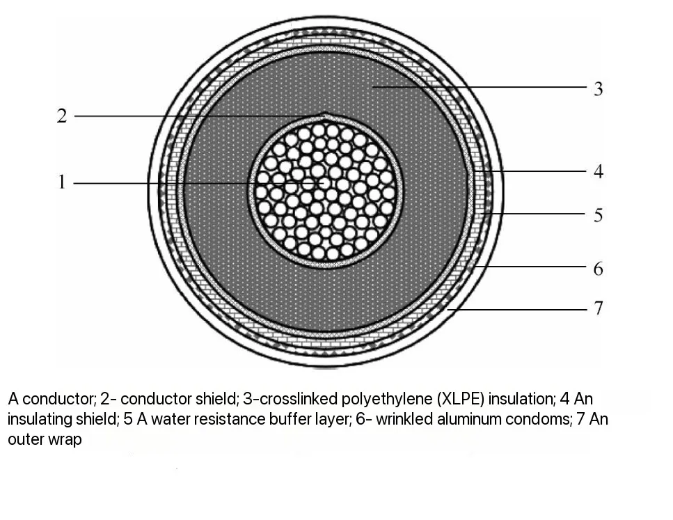
High-voltage power cables require precise quality inspection methods to ensure safety and reliability. X-ray imaging detection technology has been widely applied to examine the internal structure of cables and identify defects. However, most current applications focus on qualitative analysis, with limited studies on quantitative evaluation.
This article explores the dimensional measurement and calibration of high-voltage cables using X-ray imaging. It examines whether existing imaging systems meet the accuracy requirements for cable size testing, identifies key factors affecting measurement precision, and proposes a calibration method for improving measurement accuracy. The study verifies its findings through practical application cases, demonstrating that the proposed magnification correction method effectively enhances quantitative assessment in power cable inspections.
X-ray imaging technology is primarily used to:
Despite its advantages, X-ray imaging introduces size distortion due to image magnification and geometric transformation. This results in measurement discrepancies between the X-ray image and the actual cable dimensions. A systematic calibration method is required to ensure accurate measurements.
| Imaging Parameter | Typical Value | Impact on Measurement |
|---|---|---|
| Resolution | 2.5–6.7 lp/mm | Determines the smallest detectable feature |
| Magnification Factor | 1.02–1.20 | Affects measurement accuracy |
| Detection Angle | 0° (optimal) | Incorrect angles introduce measurement errors |
X-ray imaging enlarges cable dimensions due to geometric projection. The magnification factor (M) is calculated as follows:
As L2L2 increases, magnification effects become more pronounced, leading to size measurement errors.
Incorrect shooting angles cause shape distortion and inaccurate measurements. The ideal condition is to have the X-ray beam perpendicular to the cable’s cross-section. When the angle deviates from 90°, features such as defects appear elongated or compressed, leading to misinterpretation of their actual size.
To minimize projection errors, adjusting the X-ray source direction by 50°–130° can improve detection accuracy. In cases where defects are suspected, performing two perpendicular scans at 90° angles ensures better defect identification.
Higher resolution allows finer details to be captured, enabling more precise dimensional measurements. The clarity of an X-ray image depends on:
Blurred images introduce uncertainty, making it difficult to define edges and measure dimensions accurately.
To correct for magnification and measurement errors, two calibration methods were evaluated:
A reference scale (such as a cross-marked ruler or lead strip) is placed alongside the cable during imaging. This allows direct reading of actual dimensions from the image.
Advantages:
Disadvantages:
This method estimates the magnification factor using known cable dimensions, such as conductor diameter or insulation thickness. The actual size is calculated by dividing the measured image size by the magnification factor.
Advantages:
Disadvantages:
Comparing both methods, the magnification correction method is generally preferred for high-voltage cable inspection due to its flexibility and ease of use.
| Calibration Method | Pros | Cons |
|---|---|---|
| Reference Scale | Direct measurement, easy to implement | Requires manual placement, may interfere with images |
| Magnification Correction | No external reference needed, more practical for field tests | Requires known reference sizes, may introduce slight errors |
A 220 kV power cable experienced local deformation in its aluminum sheath due to external mechanical pressure. The X-ray image showed a significant reduction in the distance between the sheath and the insulation layer.
After applying the magnification correction method (M = 1.15), the true deformation value was determined, confirming the need for further inspection.
During routine inspection, an air void was detected inside a cable termination joint.
Although no immediate risk was identified, regular monitoring was recommended to prevent long-term degradation.
A 110 kV power cable exhibited signs of insulation degradation.
After dismantling the cable, physical measurements confirmed the X-ray findings, prompting cable replacement.
This study investigated the quantitative measurement of high-voltage cable dimensions using X-ray imaging. The key conclusions are as follows:
Further research is recommended to refine measurement uncertainty analysis and improve calibration accuracy.
High-voltage cables, X-ray imaging, dimensional measurement, calibration methods, defect analysis.
This research provides a systematic approach to improving X-ray imaging accuracy for power cable inspections, supporting enhanced quality control and maintenance strategies.