
Keep up to date with our latest company news and relevant industry knowledge.
Time: 2025-03-11 13:53:56 Source: Henan Province Jianyun Cable Co., Ltd.
With the increasing development of offshore energy resources, submarine composite cables play a crucial role in power transmission, signal communication, and control systems for underwater production facilities. However, laying submarine cables in marginal oilfields presents unique challenges due to shallow water depths, irregular seabeds, and operational constraints.
This article explores:
Through simulation modeling and practical engineering applications, this study provides valuable insights into improving the efficiency, safety, and reliability of submarine cable laying operations.
Marginal oilfields are small, scattered reservoirs that require cost-effective and flexible infrastructure. Unlike large deepwater oilfields, marginal fields demand efficient cable-laying techniques due to:
A well-planned cable-laying operation ensures:
To ensure safe and reliable cable laying, a numerical simulation was conducted using OrcaFlex software, a powerful tool for analyzing dynamic cable behavior in marine environments.
| Parameter | Value |
|---|---|
| Water Depth | 35m |
| Cable Outer Diameter | 112mm |
| Cable Unit Mass in Air | 26.6 kg/m |
| Cable Unit Mass in Water | 16.4 kg/m |
| Maximum Laying Tension | 9.0 kN |
| Minimum Laying Tension | 1.9 kN |
| Bending Stiffness | 2.59 kN·m² |
| Twisting Stiffness | 129.52 kN·m² |
➡ Objective: To analyze tension distribution, bending radius, and stability during laying operations.
| Measured Factor | Value |
|---|---|
| Maximum Tension at Topside | 9.0 kN |
| Minimum Tension at Seabed | 1.9 kN |
| Bending Radius at Overboarding Point | 3.09m |
| Seabed Departure Angle | 165.2° |
➡ Key Findings:
By adjusting laying tension and water depth, the sensitivity of cable performance was evaluated.
| Tension (kN) | Minimum Bending Radius (m) | Seabed Departure Angle (°) |
|---|---|---|
| 7.0 | 3.07 | 177.9 |
| 8.0 | 3.08 | 171.5 |
| 9.0 | 3.09 | 165.2 |
| 10.0 | 3.10 | 160.0 |
| 11.0 | 3.08 | 156.2 |
| 12.0 | 3.09 | 152.9 |
| Water Depth (m) | Minimum Bending Radius (m) | Seabed Departure Angle (°) |
|---|---|---|
| 33 | 3.09 | 162.8 |
| 34 | 3.09 | 163.8 |
| 35 | 3.09 | 165.2 |
| 36 | 3.09 | 166.1 |
➡ Conclusion:
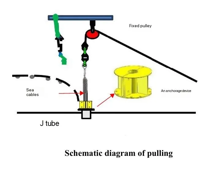
A new Ω-shaped tail-pulling method was introduced to improve final positioning.
| Traditional Pulling Method | New Ω-Shaped Method |
|---|---|
| High seabed friction | Lower friction with float-supported positioning |
| Requires more pulling force | Reduced force due to pre-planned curvature |
| Risk of damage at final anchor point | More controlled and gradual placement |
➡ Benefit: Reduces energy loss, installation time, and cable stress.
The study of submarine composite cable laying in marginal oilfields has provided valuable insights into optimizing installation procedures.
✔ Simulation-based analysis using OrcaFlex enhances laying efficiency.
✔ Sensitivity analysis confirms operational flexibility under different water depths and tension conditions.
✔ New Ω-shaped tail-pulling method reduces cable stress and improves final placement accuracy.
These advancements contribute to safer, more efficient, and cost-effective cable installations for offshore energy projects.